MARSTEK MARS I PLUS
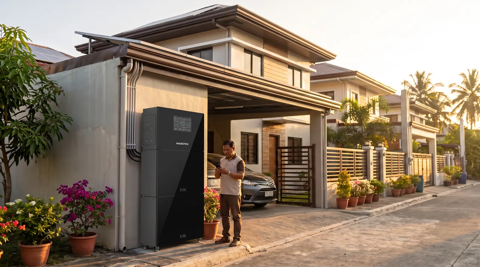
What it is: the MARS I PLUS is an all-in-one single-phase residential energy storage system. A hybrid inverter with 2 MPPT solar inputs, grid, backup (EPS), generator and EV-charger terminals sits on top of a stack of MARS I PLUS V-Boost 5.12 kWh LFP battery modules. The datasheet sells it as "6-in-1" with 5.12–30.72 kWh capacity. The Philippine SRP "full set" is 1 × 6 kW inverter + 3 batteries (15.36 kWh).
Who it's for: new solar installations and homes that want one integrated system covering solar, battery, grid, backup and generator, installed and commissioned by authorised ESS professionals.
Best for
- New solar + storage installations where no separate inverter exists ("ideal for new solar installations, no separate inverter needed" per the e-Catalog).
- Homes that want critical circuits on EPS (backup) loads with fast switchover during brownouts.
- Customers who want to grow capacity later: 1–6 battery modules per inverter (2–6 on the 6 kW model).
- Sites with a backup generator (dedicated GEN terminal) or a planned MARSTEK EV charger (EVSE terminal).
Key features
- Model range: 3.6 / 4.6 / 5 / 6 kW single-phase hybrid inverters with the MST-MARS I PLUS-5.0KBAT battery module (datasheet, manual §2.1).
- Scalable: 1–6 battery modules per inverter (6 kW model: 2–6). More than 3 batteries requires an expansion box/kit, and a single stack must not exceed 3 batteries (manual §2.3, §4.3).
- Two PV MPPTs, 125–500 V MPPT range (datasheet), 550 V max DC input.
- EPS (backup) loads vs on-grid loads (manual §2.4.1): EPS loads are the critical circuits you choose to keep powered during an outage (e.g. refrigeration, lighting, communications). On-grid loads (e.g. air conditioners, clothes dryers) run only when there is enough surplus after EPS loads are covered. The manual shows both whole-home and partial home backup wiring layouts.
- Working modes (manual §6.2.2):
- Self-Consumption: solar first, then battery, then grid. Surplus is exported only if anti-backflow is disabled.
- AI Mode: select your electricity provider and keep the system online; the AI optimises energy flow. Supported providers are listed on MARSTEK's website.
- Manual Mode: weekly schedule of up to 6 time slots, each set to Charge, Discharge or Self-Consumption. Unscheduled time is Standby (no battery discharge; surplus PV still charges).
- Ports (manual §5.1): GRID, EPS, GEN (single-phase generator), EVSE (MARSTEK EV charger) and EVSE CAN, PV1/PV2, DC-BUS / COM (V2X), LAN, RS485 (external EMS / heat pump), METER/CT, PARALLEL, DRM, DI1–DI4, DO1/DO2, 5 V/12 V auxiliary supply, PV switch and system switch.
- Display: 10.1" LCD plus app (datasheet).
- Datasheet claims: "Expandable to 24 kW output", IP65, 10-year warranty, MARSTEK AI optimisation.
Product views
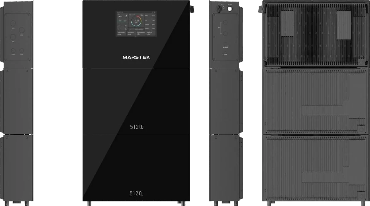
Specifications
Inverter: datasheet table
Source: MARS I PLUS Single-Phase datasheet, spec page (transcribed from the rendered image).
| Specification | 3.6KSP | 4.6KSP | 5KSP | 6KSP |
|---|---|---|---|---|
| Model | MST-MARS I PLUS-3.6KSP | MST-MARS I PLUS-4.6KSP | MST-MARS I PLUS-5KSP | MST-MARS I PLUS-6KSP |
| PV input | ||||
| Max. PV power | 7.2 kW | 9.2 kW | 10 kW | 12 kW |
| Max. DC input voltage | 550 V | 550 V | 550 V | 550 V |
| Nominal DC input voltage | 360 V | 360 V | 360 V | 360 V |
| Start-up voltage | 150 V | 150 V | 150 V | 150 V |
| MPPT voltage range | 125–500 V | 125–500 V | 125–500 V | 125–500 V |
| Number of MPP trackers | 2 | 2 | 2 | 2 |
| PV strings per MPPT | 1 | 1 | 1 | 1 |
| Max. input current per MPPT | 16 A | 16 A | 16 A | 16 A |
| Max. short-circuit current per MPPT | 20.8 A | 20.8 A | 20.8 A | 20.8 A |
| AC output and input (on-grid) | ||||
| Nominal output power | 3.6 kW | 4.6 kW | 5 kW | 6 kW |
| Max. output apparent power | 4 kVA | 5.1 kVA | 5.5 kVA | 6.6 kVA |
| Nominal output current | 15.7 A | 20 A | 21.7 A | 26.1 A |
| Max. output current | 18 A | 23 A | 25 A | 30 A |
| Nominal output voltage | 230 V | 230 V | 230 V | 230 V |
| Nominal grid frequency | 50 / 60 Hz | 50 / 60 Hz | 50 / 60 Hz | 50 / 60 Hz |
| Power factor | 0.8 leading ~ 0.8 lagging | ← | ← | ← |
| Total current harmonic distortion | THDi <3% | ← | ← | ← |
| Max. input apparent power | 5.9 kVA | 7.5 kVA | 7.5 kVA | 7.5 kVA |
| Max. input current | 25.7 A | 32.6 A | 32.6 A | 32.6 A |
| Efficiency | ||||
| Max. efficiency | 97.60% | 97.60% | 97.60% | 97.60% |
| European efficiency | 97.10% | 97.10% | 97.10% | 97.10% |
| MPPT efficiency | 99.60% | 99.60% | 99.60% | 99.60% |
| Battery conversion efficiency | 97.00% | 97.00% | 97.00% | 97.00% |
| Generator | ||||
| Max. input apparent power | 5.4 kVA | 6.9 kVA | 7.5 kVA | 7.5 kVA |
| Nominal input voltage | 230 Vac | 230 Vac | 230 Vac | 230 Vac |
| Frequency | 50 / 60 Hz | 50 / 60 Hz | 50 / 60 Hz | 50 / 60 Hz |
| Max. input current | 23.5 A | 30 A | 32.6 A | 32.6 A |
| AC output (backup) | ||||
| Nominal output power | 3.6 kW | 4.6 kW | 5 kW | 6 kW |
| Peak output current (1 s) | 150%–200% | ← | ← | ← |
| Nominal output voltage | 230 V | 230 V | 230 V | 230 V |
| Frequency (row labelled "Power Factor" in the datasheet) | 50 / 60 Hz | ← | ← | ← |
| Total voltage harmonic distortion | THDv <3% | ← | ← | ← |
| Backup switch disruption time | <10 ms | ← | ← | ← |
| Battery connection | ||||
| Battery module model | MST-MARS I PLUS-5.0KBAT | ← | ← | ← |
| Modules per inverter | 1–6 pcs | ← | ← | ← |
| Nominal voltage of battery module | 400 V | ← | ← | ← |
| Voltage range of battery module | 350–550 V | ← | ← | ← |
| Protection | Insulation monitoring, residual current monitoring, anti-islanding, DC reverse-polarity protection, AC OV/OC/SC protection, Type II DC/AC surge protection | |||
| General data | ||||
| Dimensions (W/H/D) | 628 × 195 × 398 mm | ← | ← | ← |
| Weight | 35 kg | ← | ← | ← |
| Storage temperature | -40 °C to 70 °C | ← | ← | ← |
| Operating temperature | -25 °C to 60 °C | ← | ← | ← |
| Relative humidity | 0–100% | ← | ← | ← |
| Max. operating altitude | 4,000 m, derating from 2,000 m | ← | ← | ← |
| Cooling | Natural cooling | ← | ← | ← |
| Standby power consumption | <35 W | ← | ← | ← |
| Ingress protection | IP65 | ← | ← | ← |
| Noise level | <30 dB | ← | ← | ← |
| Display | 10.1" LCD, App | ← | ← | ← |
| Communication | RS-485 for meter, RS-485 for heat pump, parallel CAN × 2, DC BUS CAN, RS-485 for EMS, Wi-Fi / Bluetooth / Ethernet, battery access CAN (internal) | |||
| General I/O | DI × 4, DO × 2, CT × 3, +5 V power, +12 V power, DRAM | |||
| Standards | ||||
| Safety | IEC/EN 62109-1 | |||
| EMC | IEC/EN 61000-6-1~4 Class B | |||
| On-grid | EN 50549-1:2019, VDE 4105:2018, VDE 0126-1-1, EN 50438, Italy CEI 0-21 |
"←" means the same value as the column to the left (the datasheet merges these cells across all models).
Additional values from the manual
Source: MARS I PLUS user manual, Appendix D Parameters. The manual names the inverters MST-3.6KSH-M0 … MST-6KSH-M0 in the parameter table and MST-3.6KSP-M0 … MST-6KSP-M0 elsewhere.
| Specification | 3.6 kW | 4.6 kW | 5 kW | 6 kW |
|---|---|---|---|---|
| Backup max. output apparent power | 3.8 kVA | 4.8 kVA | 5.3 kVA | 6.3 kVA |
| Backup rated output current | 15.7 A | 20.0 A | 21.7 A | 26.1 A |
| Backup max. output current | 23.4 A (5.4 kW, 1 s) | 30 A (6.9 kW, 1 s) | 32.6 A (7.5 kW, 1 s) | 39.1 A (9 kW, 1 s) |
| EVSE output (rated power / current) | 3.6 kW / 15.7 A | 4.6 kW / 20.0 A | 5 kW / 21.7 A | 6 kW / 26.1 A |
| Specification (all models) | Value per manual |
|---|---|
| Grid voltage range (on-grid) | 170–280 V |
| Grid frequency range | 45–55 Hz (50 Hz) / 55–65 Hz (60 Hz) |
| Generator input voltage / frequency range | 170–280 V / 30–70 Hz |
| Anti feed-in protection | Configurable |
| Backup overload behaviour | 105–125% load: alarm and shutdown after 10 min; 125–150%: after 1 min; above 150%: after 1 s |
| DC terminal type / PV DC isolation switch | Push-in / standard |
| Overvoltage category | DC: Class II; AC: Class III (general) |
| Battery parameters | LFP, rated 400 V, range 350–500 V, max. charge/discharge power 6 kW, max. charge/discharge current 17.1 A, capacity 5.12 kWh (per module) |
| Battery module dimensions (drawing) | 628 × 196 mm footprint; drawing heights 390 mm / 417 mm / 445 mm (details on the manual's drawing) |
| Battery handling | Battery module is marked "> 55 kg"; carry with the handles |
| Storage conditions (§3.2) | -40 to 70 °C with 5–95% RH, and -20 to 35 °C with 10–80% RH, as listed for the inverters and the battery module |
| Pollution degree | PD2 |
| Warranty (manual / warranty card) | 10 years. Confirm local warranty terms with Silvera Solar Power. |
| Item | Datasheet | Manual |
|---|---|---|
| MPPT voltage range | 125–500 V | 120–500 V |
| DC input voltage | Max 550 V, nominal 360 V | Lists 550 V and 650 V for max / rated DC input (extracted order unclear) |
| Backup THDv | <3% | <2% |
| Battery module voltage range | 350–550 V | 350–500 V |
| Inverter depth | 195 mm (628 × 195 × 398) | 196 mm (628 × 196 × 398) |
| Altitude | 4,000 m, derating from 2,000 m | ">2000 m derating" |
| Communication | Long list (see table) | Wi-Fi, LAN, CAN, RS-485 |
| Inverter model suffix | KSP | KSH and KSP |
| Battery model | MST-MARS I PLUS-5.0KBAT | 5.0KBAT and 5KBAT |
Prefer the latest engineering document when designing a system, and confirm with MARSTEK / Silvera technical support before relying on edge values (especially PV string voltage).
The SRP flyer labels the parts "MARS I INVERTER" and "MARS I BATTERY". The engineering documents call them MARS I PLUS. Treat them as the same product family, but confirm part numbers on the quotation.
Price (SRP)
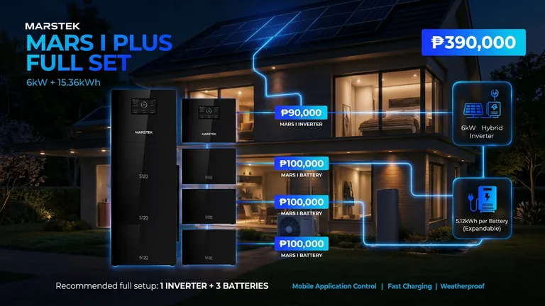
Per the SRP flyer in Drive:
| Item | SRP |
|---|---|
| MARS I PLUS Full Set: 1 × 6 kW hybrid inverter + 3 × 5.12 kWh batteries | ₱390,000 (original ₱445,000) |
| MARS I inverter (individual) | ₱90,000 |
| MARS I battery (each) | ₱100,000 |
The flyer does not say whether installation is included, so clarify this on every quotation. Confirm current pricing with Silvera Solar Power before quoting. See the price list.
Installation & safety
The manual states the whole system shall be installed and configured by professional technicians who are company-authorised, familiar with local standards and electrical safety regulations, formally trained and certified in ESS installation, and experienced enough to identify risks and complete commissioning and documentation. After installation, users must not relocate components, change wiring or non-user settings, or tamper with the smart meter, CT or distribution-box connections.
From the MARS I PLUS manual (§4 Mechanical installation, symbols and safety sections):
- Indoor installation is strongly recommended. If outdoor installation is unavoidable, place the unit under a protective structure (e.g. a waterproof canopy) against prolonged sun, rain, snow or hail.
- Avoid flammable liquids, gases or aerosols; sealed enclosures or cramped spaces; coastal or high-salt air; excessive dust, conductive pollution or corrosive fumes. Ensure enough airflow around the heat sinks.
- Mounting structure: non-combustible or fire-resistant (concrete, brick, metal), strong enough for the whole system's weight for its lifetime, and solid enough for drilling and anchoring.
- Clearances: the installation-space diagram shows minimum clearances of ≥300 mm, ≥500 mm, ≥500 mm and ≥800 mm around the system. Follow the manual's drawing for which side each applies to.
- Stacking: maximum 3 batteries per stack. For more than 3 batteries an expansion box/kit is needed. Battery modules weigh over 55 kg, so use the handles and handle latches.
- Required PPE: goggles, protective gloves, safety hat, dust mask, insulating gloves and insulating shoes. Installation tools listed: power drill, screwdriver set, marker, tape measure, adjustable pipe wrench, ferrule crimp tool, level, wire stripper, wire cutter, hammer, heat-shrink tube, crimping pliers, RJ45 crimp tool, cable ties and heat gun.
- High voltage: do not open the casing while operating. Internal components retain hazardous energy; wait at least 10 minutes after power-off before work. Hot surfaces in the heat-sink area.
- Unauthorised use of the auxiliary 5 V/12 V supply interface is prohibited (risk of short circuit or overload).
- Storage over 6 months requires inspection and, for batteries, a charge-discharge maintenance cycle.
Related tutorials
- MARS I PLUS installation overview
- MARS I PLUS troubleshooting
- Brownout preparedness
- Backup calculator
Sources
- MARS I PLUS Single-Phase datasheet (Drive): inverter spec table, features, images
- MARS I PLUS user manual (Drive): system scaling, modes, ports, Appendix D parameters, installation rules
- MARSTEK Flyers – SRP (Drive): full-set and component prices
- MARSTEK AI e-Catalog 2026 (Drive): recommended 1 inverter + 3 batteries setup, positioning (see catalog capture)