MARS I PLUS installation overview
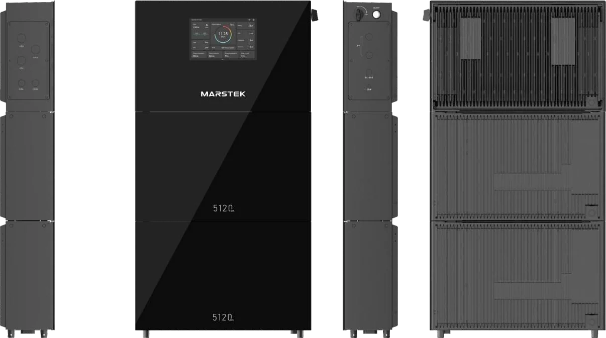
The MARSTEK MARS I PLUS is a single-phase hybrid inverter plus stackable "V-boost" battery home energy storage system. This page summarises the MARS I PLUS user manual V1.4 (26 May 2026) so Silvera staff and installers know what an installation involves. It is an overview, not a replacement for the manual, which has the full drawings, torque marks, pin-outs and dimensions.
The manual states: "The whole system shall be installed and configured by professional technicians who are:"
- Company authorized;
- familiar with local standards and electrical safety regulations;
- formally trained and certified in the installation of energy storage systems (ESS);
- experienced in ESS installation, able to identify and reduce risks, and responsible for all commissioning and documentation.
After installation, users must not move components, change wiring or non-user settings, or touch the smart meter, CT or distribution-box connections. "Only authorized personnel may perform these tasks." Before the system is energised for the first time, a certified installer must complete the commissioning checklist.
1. System overview
| Component | Models (from manual section 2.1) |
|---|---|
| Single-phase hybrid inverter | MST-3.6KSH-M0 (3.6 kW), MST-4.6KSH-M0 (4.6 kW), MST-5KSH-M0 (5 kW), MST-6KSH-M0 (6 kW) |
| Battery | MST-MARS I PLUS-5KBAT, "MARS I PLUS V-boost Battery 5.12 kWh" |
Key figures from the manual's Appendix D (per inverter model):
| Parameter | 3.6 kW | 4.6 kW | 5 kW | 6 kW |
|---|---|---|---|---|
| Max. PV power | 7.2 kW | 9.2 kW | 10 kW | 12 kW |
| Backup (EPS) rated output | 3.6 kW | 4.6 kW | 5 kW | 6 kW |
| On-grid rated output | 3.6 kW | 4.6 kW | 5 kW | 6 kW |
Shared values: PV max. DC input 550 V, MPPT range 120–500 V, 2 MPPTs; backup output 230 V, 50/60 Hz, switch-over time less than 10 ms; grid 230 V L/N/PE, 170–280 V; battery LFP, 400 V nominal, 5.12 kWh per module; inverter IP65, natural cooling, 628 × 196 × 398 mm, 35 kg; display LCD + app; communication Wi-Fi, LAN, CAN, RS-485.
- Inverter model codes appear as …KSH-M0 in section 2.1 and Appendix D, but as …KSP-M0 in the compatibility table, dimension drawings and grid-code table.
- The battery appears as both MST-MARS I PLUS-5KBAT and MST-MARS I PLUS-5.0KBAT.
- The inverter packing-list artwork shows a Quick Guide titled "MARS I PLUS Three Phase Energy Storage System", while the manual itself covers the single-phase system.
Confirm the exact model codes on the shipping labels against the order.
2. Battery count and expansion rules
From manual section 2.3, "Compatible Components and System Scaling":
| Inverter | Inverters per system | MARS I PLUS 5.0 kWh batteries |
|---|---|---|
| 3.6 kW | 1 | 1 – 6 |
| 4.6 kW | 1 | 1 – 6 |
| 5 kW | 1 | 1 – 6 |
| 6 kW | 1 | 2 – 6 |
- More than 3 batteries needs an expansion kit / expansion box.
- No more than 3 batteries in one stack. The manual says more "may be unsafe".
- Each battery module weighs more than 55 kg (manual drawing), so plan for a two-person lift.
The SRP flyer in Drive shows a MARS I PLUS full set = 1 inverter + 3 batteries (₱390,000, originally ₱445,000; MARS I inverter ₱90,000, each MARS I battery ₱100,000). Three batteries is the most that fits in one stack without the expansion box. Prices are per the SRP flyer in Drive. Confirm current pricing with Silvera Solar Power before quoting.
3. EPS (backup) loads vs on-grid loads
The inverter has an Emergency Power Supply (EPS) port, so it manages two types of load (manual section 2.4.1):
| Load type | What goes here | Behaviour |
|---|---|---|
| EPS (backup) loads | Critical circuits that must stay on during an outage, e.g. refrigeration, lighting, communications | Battery and solar energy go to EPS loads first. These are the circuits kept running during a brownout. |
| On-grid loads | Normal circuits in the main panel downstream of the CT/meter, e.g. air-conditioners, clothes dryers | Can draw from both inverter and grid. Powered by the system only when there is surplus after EPS loads are met. |
The wiring diagrams show Partial Home Backup: Grid → CT/Meter → distribution box (non-backup loads), with the inverter's EPS output feeding a separate EPS distribution box. Solar panels, an optional generator, optional external EMS and Wi-Fi/Ethernet are also shown.
The manual says the system must not be connected to elevators, essential emergency medical equipment, fire and rescue equipment, or "any device that, once stopped, may pose a threat to human safety or cause serious economic losses."
4. Site requirements
From manual section 4.1:
- No flammable liquids, gases, aerosols or excess combustible material nearby.
- Enough natural or forced airflow, especially around the heat sinks. No sealed enclosures or cramped spaces.
- Indoor installation is strongly recommended. If it must go outdoors, put it under a protective structure (e.g. a waterproof canopy) to avoid long direct sun, rain or hail.
- Keep away from coastal / high-salt-air locations. Salt corrosion can severely damage components. This matters for sites near the Batangas coast.
- Avoid heavy dust, conductive pollution and corrosive fumes.
- The mounting structure must be non-combustible or fire-resistant (concrete, brick, metal), strong enough for the full system weight for its lifetime, and solid enough to drill and anchor into.
- Clearances shown in the manual's drawing: ≥ 300 mm, ≥ 500 mm, ≥ 500 mm, ≥ 800 mm around the system. Read the manual diagram to see which side each value applies to.
5. Mechanical installation (overview)
Everything below is for authorised, ESS-certified installers only. Power off the whole system, including grid and PV, before any cable work. The manual says to use the official website's documentation and videos for mechanical installation details.
Pre-installation check
Check the outer packaging for holes, cracks or crushing. Confirm the label model matches the order. Unpack and check every item against the inverter packing list (handles, wiring cover plates, adjustable feet, wall bracket, battery plug, handle latches, M8 expansion bolts, parallel plug, wire ferrules, screws, CT with cable, quick guide, user manual, warranty card) and the battery packing list (wall brackets, M8 expansion bolts, M6 module-stack screws, M6 wall-bracket screws).
Get PPE and tools ready
PPE: goggles, protective gloves, safety hat, dust mask, insulating gloves, insulating shoes. Tools: power drill, screwdriver set, marker, tape measure, adjustable pipe wrench, ferrule crimp tool, level, wire stripper, wire cutter, hammer, heat-shrink tube, crimping pliers, RJ45 crimp tool, cable ties, heat gun. The manual says tools must be inspected and undamaged (no scratched insulation).
Install the bottom battery
Lay the bottom battery on its back on soft padding. Remove the upper and lower connector covers and fit the bottom battery plug. Optionally screw in the 4 adjustable feet. Carry it to the site using the handles (more than 55 kg, and make sure all handle latches are fitted). Level the feet with a wrench and spirit level. Fit the wall bracket, mark and drill the holes, and optionally connect the enclosure ground wire.
Stack additional batteries
For each extra battery: lay it on padding, remove the connector covers, stack it with the connectors aligned, lock the fixing screws, fit the wall bracket and optionally connect the enclosure ground. Maximum 3 batteries per stack.
Install the inverter on top
Lay the inverter on padding. Fit the handle latches on top with the supplied screws and remove the connector cover. Lift it onto the battery stack with the inverter connector aligned to the battery connector, then lock the fixing screws. Connect and tighten the enclosure ground wire. After all connections are done, fit the window plate and tighten the PG glands.
6. System connection (overview)
Ground first
After mechanical installation, connect the enclosure grounding (PE) cable first. The manual says inverter grounding is necessary and battery grounding is highly recommended.
Prepare and connect cables
The manual's cable table (section 5.2.1):
| Cable | Specification | Connector |
|---|---|---|
| PE cable | 12–14 AWG hook-up wire (green/yellow) | Ring connector, 1/4″ stud |
| AC power cable | 8–10 AWG 3-core cable | Crimp ferrule, 8 AWG |
| DC power cable | 10–12 AWG hook-up wire (red +, black −) | Crimp ferrule, 10 AWG |
| Digital signal cable | 20–22 AWG hook-up wire | Crimp ferrule, 20 AWG |
| RS485 communication | 20–22 AWG twisted shielded 2-core | Crimp ferrule, 20 AWG |
| Additional power supply (5 V/12 V) | 20–22 AWG hook-up wire (red +, black −) | Crimp ferrule, 20 AWG |
| Network | CAT6 | RJ45 8P8C |
Main ports: GRID, EPS, GEN (single-phase generator), PV1/PV2, METER/CT, PARALLEL, LAN, RS485, DO1/DO2, DI1–DI4, DRM, EVSE + CAN (MARSTEK EV charger), DC-BUS/COM (V2X), 5V/12V, plus the PV switch and system switch. The manual warns that unauthorised users must not use the auxiliary interfaces, because short circuits or overloads can cause irreparable damage. RJ45 pin definitions differ between ports, so follow the manual's pin table.
Install the CT
- Open the CT clamp and put it around a single conductor of the main grid cable.
- The arrow on the CT must point toward the grid (utility) side. Wrong orientation gives reversed power readings.
- Close the clamp until it clicks, with no gap between the halves.
- Connect the CT to the METER/CT port with a network cable. Maximum cable length is 25 m.
The manual says the system is also compatible with third-party CTs and smart meters, and refers to MARSTEK's website for the supported models. It does not list them.
7. Commissioning
Run the first-energisation checklist (certified installer)
| Check | What to verify |
|---|---|
| Mechanical installation | All units securely mounted; ventilation clearances kept; site meets requirements |
| Cable routing | Cables routed and fastened; no pinching, cuts or abrasion; away from sharp edges and heat |
| Grounding | PE cable connected and tight; building grounding system verified |
| Connections | All AC/DC connections tight; DC polarity correct (PV, battery); communication cables seated and locked |
| AC grid & loads | Phase, neutral, earth on correct terminals; backup load circuit identified; all AC breakers OFF before start-up |
| Battery | All modules installed and interconnected; no damage, swelling or leakage |
| Final area check | Tools and loose parts removed; covers installed and closed |
Power on
- Battery ON: press and hold the button for more than 3 seconds until the indicator lights, then release.
- PV switch (rotary knob): keep it OFF during installation and commissioning. Turn it ON only after all connections are verified.
First-boot configuration on the display
- Select language, then read and accept the privacy policy and user agreement.
- Connect to the network by Wi-Fi or Ethernet. The manual says a stable internet connection is needed for setup.
- Basic settings:
- Grid standard: choose from Appendix A.
- Battery quantity: number of modules installed.
- Mode: Self-Consumption, AI or Manual.
- Backup power setting: reserve SOC, adjustable 30%–90%.
- CT configuration: choose Wired CT (or follow the wireless-CT section).
- Activate. The system runs a self-inspection (PV input, AC, battery, network, electric meter, device). Any item marked "Abnormal" can be tapped to see possible causes and solutions. Fix it before regular use.
Appendix A lists 15 European and Australian/New Zealand grid codes, each marked "Supported" or "Not Supported", under headers for MST-3.6/4.6KSP-M0 and MST-5/6KSP-M0. The text extraction does not clearly show which column each mark belongs to, so check the original table. No Philippine grid standard is listed. Before commissioning a PH installation, confirm the correct grid-code setting with MARSTEK / Silvera technical support.
8. Working modes (manual section 6.2.2)
| Mode | Behaviour |
|---|---|
| Self-Consumption | Solar powers home loads first, surplus charges the battery, and surplus is exported only if the battery is full and anti-backflow is disabled. At night or in low PV, the battery powers loads until it reaches its DoD setting, then the grid takes over. "Solar power comes FIRST, battery is energy bank, grid is backup plan." |
| AI Mode | Select your electricity provider and keep the system online. AI optimises energy flow. Supported providers are listed on MARSTEK's website (the manual does not list any Philippine providers). |
| Manual | Weekly schedule with up to 6 time slots: Charge (PV + grid if needed), Discharge (battery + PV, can export), Self-Consumption (for that slot). Unscheduled time = Standby (battery won't discharge, but surplus PV still charges it). |
OTA updates: keep the internet connection stable, never power off or disconnect the batteries during an upgrade, and update when grid power is stable and backup power isn't needed. The system may restart, and backup may be unavailable during the update. If it stays unresponsive for more than 2 hours, contact support.
App: the manual lists Google Play, the App Store and the download link https://eu.hamedata.com/ems/apk/marstek/index.html, plus QR codes for the app user guide and the display guide.
9. Power off, maintenance and emergencies
- Battery OFF: hold for more than 3 seconds until the relay clicks. Wait at least 10 minutes after the indicator goes off before doing anything else, so the capacitors can discharge. The battery can only shut down when there is no grid and no PV input. It wakes up automatically if either returns.
- If the system is off-grid with no AC or PV input, the manual recommends shutting it down, or charging it regularly to avoid a low-battery state.
- Monthly visual check: corrosion on visible terminals, alarm codes on the display, loose cables, and a clean surrounding area.
- Cleaning: system OFF, soft dry cloth only. No liquid cleaners, solvents or sprays.
- Fire: evacuate, call emergency services, and if safe, shut off AC and DC at the main disconnects. Tell firefighters an ESS is on site. Do not use water.
- Flood: do not touch the system if water has reached it. Do not restart after water recedes until a qualified technician has inspected it.
Related pages
Sources
- MARS I PLUS user manual V1.4 (Drive): primary source
- MARS I PLUS single-phase datasheet (Drive)
- SRP flyer (Drive): full-set pricing note only